My Dragon cartridge boards (actually work!!!)
Re: My Dragon cartridge boards (actually work!!!)
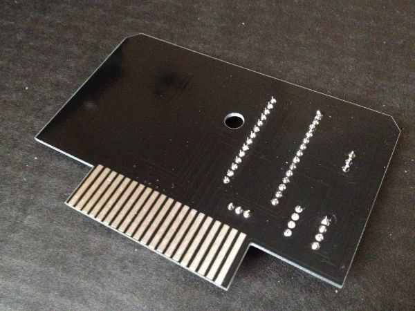
That's not bad, but it would be better if you could take another photo from above, with the camera directly facing the board (so we can more clearly see all the interconnecting tracks).
Re: My Dragon cartridge boards (actually work!!!)
Would it be easier if I just post the PCB images from the design software? Waiting on a new power supply for my laptop but I suspect it'd be a lot clearer than trying to make out black tracks between a black ground fill under a black solder mask. 
Re: My Dragon cartridge boards (actually work!!!)
No. A quick photo taken from the correct angle would suit me just fine!Rink wrote:Would it be easier if I just post the PCB images from the design software? Waiting on a new power supply for my laptop but I suspect it'd be a lot clearer than trying to make out black tracks between a black ground fill under a black solder mask.
Re: My Dragon cartridge boards (actually work!!!)
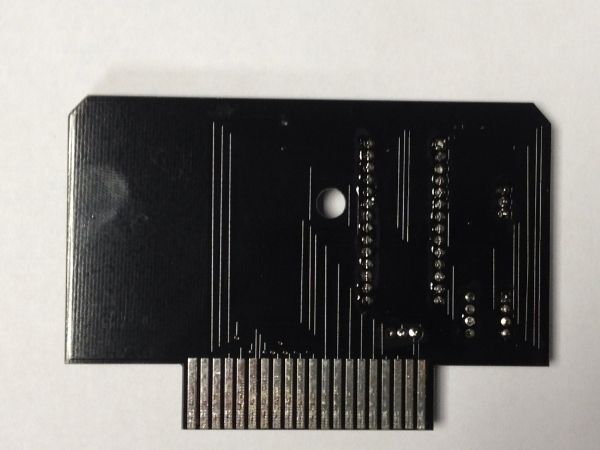
Please place the PCB in the center of an A4 sheet of white paper, and take a photo with the camera directly facing the solder side. This quick, simple task is all I'm asking for.
Regards,
Steve
Regards,
Steve
Re: My Dragon cartridge boards (actually work!!!)
Lol. Will do mate.zephyr wrote:Please place the PCB in the center of an A4 sheet of white paper, and take a photo with the camera directly facing the solder side. This quick, simple task is all I'm asking for.
It's pretty gloomy here today so will have to source a few extra lights and things - or a better camera.
Re: My Dragon cartridge boards (actually work!!!)
Any use to you? Not that it matters, it's as good as it's going to get. 
Re: My Dragon cartridge boards (actually work!!!)
That's perfect. Thanks! 
Re: My Dragon cartridge boards (actually work!!!)
GOD DAMN!!!
I've just spent a few days trying to make a second (slightly better) ROM programmer, and in the process discovered a mistake on my boards. I forgot to check if the NAND gates I was using needed a pull up resistor to turn 0s into 1s. It turns out that they do - which means that OE* on the rom/ram chips was always getting enabled.
This is interesting in two ways: firstly, it means that those Alliance SRAM chips are super good at detecting movement on WE* and initiating a write cycle even when OE* goes low 20ns later. And secondly, it's a good reason why I couldn't get the Dragon 32 to write to a 28 series EEPROM even though it looked like it should...
With a resistor in place, the Dragon CAN write to those roms and so now I have a non-volatile RAM pack for the Dragons. It also means that the little trick of using DrBinCas to load a ROM image from tape makes the Dragon 32 into a rom programmer... Meaning I didn't need to spend the last few days building another programmer.
Life is funny sometimes.