My Dragon cartridge boards (actually work!!!)

Hardware Hacking, Programming and Game Solutions/Cheats
Rink
Posts: 236
Joined: Mon Sep 05, 2011 7:01 pm

My Dragon cartridge boards (actually work!!!)

Post by Rink »

Thought I'd post this just because I got a project finished and they work!!! That's pretty rare for me at the minute. :)

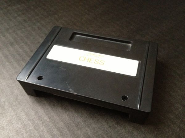
I have another Dragon project on the go, and these were kind of a spin off from that. Here we have a simple Dragon 32 cartridge board which accepts either a 28 series eeprom or a range of SRAM chips. I made them to fit inside a Dragon Data cartridge case.

Image

Image

Image

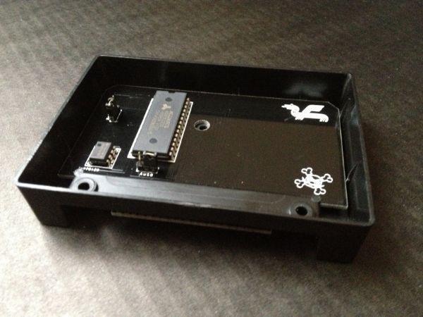
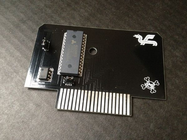
On the left, there's a jumper to disconnect the write signal - the Dragon can't actually write to the eeproms anyway (some kind of timing issue it seems) but I figured this was a good idea just in case. Down near the cartridge connectors there's another jumper to enable/disable the autostarting of ROMs.

The board pictured actually has a 32Kx8 SRAM chip in there. So it fills the 0xC000 - 0xFEFF range with near enough an extra 32K 16K of RAM. Not quite sure what you'd use that for; but as a slight side-benefit to the project, you can run a ROM image through drbincas e.g. drbincas ghost.rom GHOSTATK 41952 41952 and then load into the Dragon like you normally do your cassette files.

Pretty basic stuff - but I'm chuffed they actually work.

Edit: Maths fail - 0xC000 - 0xFEFF is 16K not 32K as I wrote.
Last edited by Rink on Wed Feb 27, 2013 10:24 am, edited 1 time in total.
User avatar
robcfg
Posts: 1532
Joined: Sat Apr 04, 2009 10:16 pm
Location: Stockholm, Sweden
Contact:

Re: My Dragon cartridge boards (actually work!!!)

Post by robcfg »

Hey! Awesome Work!

I love the black PCB with the Dragon Data logo and the skull and crossbones, hehe :mrgreen:

So, if i put an eprom chip instead of the ram chip, would it work like an standard cartridge?
Rink
Posts: 236
Joined: Mon Sep 05, 2011 7:01 pm

Re: My Dragon cartridge boards (actually work!!!)

Post by Rink »

Cheers mate.
robcfg wrote:I love the black PCB with the Dragon Data logo and the skull and crossbones, hehe :mrgreen:
Yeah, those black PCBs are just sick. I love them to bits although I've seen red PCBs recently which look great too. Fritzing do them in white, and OSH Park even do purple ones... There's really no excuse for boring green solder mask anymore. :D except you could argue that the extra cost of the coloured mask is a complete waste of money when you're going to hide the board in a case. :D
So, if i put an eprom chip instead of the ram chip, would it work like an standard cartridge?
Yep, I have two with EEPROMs in which work great. Like an Atmel AT28C64. I wish you could have the Dragon write to EEPROM but it isn't working. Maybe I'll use the space on the right half of the board for a battery backup circuit to go with SRAMs instead.
Sarah
Posts: 177
Joined: Wed Apr 13, 2011 3:36 pm
Contact:

Re: My Dragon cartridge boards (actually work!!!)

Post by Sarah »

That's great looking - so neat! :D
prime
Posts: 267
Joined: Fri Apr 10, 2009 1:40 am

Re: My Dragon cartridge boards (actually work!!!)

Post by prime »

So how are you reading the EEPROM as a matter of interest ?

Cheers.

Phill.
linville
Posts: 129
Joined: Mon Feb 13, 2012 11:01 pm

Re: My Dragon cartridge boards (actually work!!!)

Post by linville »

So, writing to a RAM in the cartridge slot works on the Dragon? I've been told that the SAM in the CoCo doesn't generate a write signal for the cartridge area...
Rink
Posts: 236
Joined: Mon Sep 05, 2011 7:01 pm

Re: My Dragon cartridge boards (actually work!!!)

Post by Rink »

linville wrote:So, writing to a RAM in the cartridge slot works on the Dragon? I've been told that the SAM in the CoCo doesn't generate a write signal for the cartridge area...
Yep. I don't know anything about CoCos but the Dragon definitely does.
Rink
Posts: 236
Joined: Mon Sep 05, 2011 7:01 pm

Re: My Dragon cartridge boards (actually work!!!)

Post by Rink »

prime wrote:So how are you reading the EEPROM as a matter of interest ?
The super lazy way...

From memory (Cartridge -> ROM):
!CTS (pin 32) is connected to the ROM's chip enable.
R/!W (pin 18) is connected via the jumper to Write Enable.
R/!W (pin 18) is connected through a NAND gate (wired to invert) to Output Enable*

Addresses A0-A14 are connected to the relevant input on the ROM. Note: this means that ROM/RAM's which don't have A14/A13 (e.g. 8K ones) must have those pins not connected internally. Some SRAM chips use A13 as a second chip enable which (I tried it accidently) means that half the RAM would be disabled for bits of the cartridge address range.

The address wiring is bad of course - the available 16K cartridge address range on the Dragon would require a 32K ROM/RAM chip if A14 was connected. But there were reasons why I did it this way - mostly laziness.

*I have billions of these little NAND ICs so I use them for everything regardless of whether there's a better solution. :)
zephyr
Posts: 1474
Joined: Mon Jul 21, 2008 1:18 am

Re: My Dragon cartridge boards (actually work!!!)

Post by zephyr »

This is a very interesting little project. 8-) I would like to ask you a few very simple (non-technical) questions.

(1) I know it was your own design, but exactly how much did it cost you for the PCB?

(2) How much did it cost for the components?

(3) Who made the actual PCB for you?


And now a small request: Please upload a picture of the underside (solder side). I'm pretty sure that most people would want to see the solder side of that very interesting looking board.
Rink
Posts: 236
Joined: Mon Sep 05, 2011 7:01 pm

Re: My Dragon cartridge boards (actually work!!!)

Post by Rink »

zephyr wrote:This is a very interesting little project. 8-) I would like to ask you a few very simple (non-technical) questions.
Thanks mate.

(1) I know it was your own design, but exactly how much did it cost you for the PCB?
They came in at a truly horrendous £4.30 each (excluding any shipping costs + tax). The problem is the size of them - they're slightly too big for the price bracketing used by the PCB fab (see below). If they weren't made to fit wobble-free in a standard Dragon Data case then they'd be like half that cost.

(2) How much did it cost for the components?
Baring in mind I wasn't buying in bulk for production...
EEPROMs (8Kx8) were about £4.80 each / SRAMs (32Kx8) were £1.28
NAND IC - hard to say. About £0.20p
Pin strips er... pennies I guess. (2 x 3w)
PC motherboard jumpers - £0.11p each (x2)
I also didn't use sockets from the ROMs because I'm programming through a homebrew programmer with a card edge connector; no socket on the NAND because they're cheaper than the sockets. :D

(3) Who made the actual PCB for you?
iTeadStudio in China. Amazing service.
And now a small request: Please upload a picture of the underside (solder side). I'm pretty sure that most people would want to see the solder side of that very interesting looking board.
Sure thing. Will do as soon as I get home (I didn't think to take one) - no passing judgement on my soldering abilities mind. ;)

Edit: forgot the NAND.
Post Reply